Ferroelectric Capacitor
Ferroelectric Capacitor Fabrication and Characterization
A side project was learning how to improve the quality of the ferroelectric thin films we fabricated in our lab using poly(vinylidene fluoride-co-hexafluoropropylene) (PVDF-HFP). Samples were fabricated with the following structure to avoid edge affects:
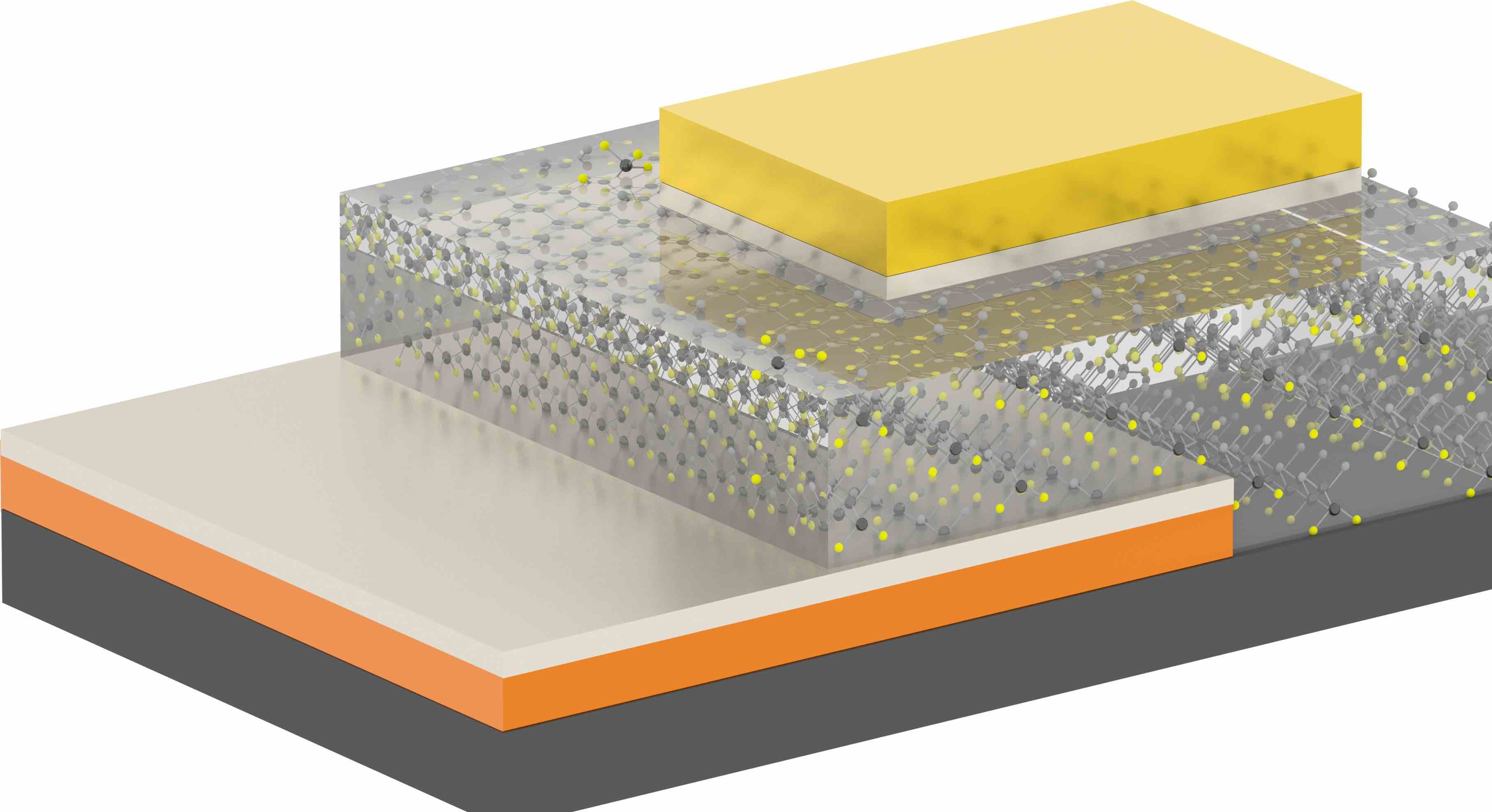
Ferroelectric capacitor structure visualization. The SiO2 wafer substrate is shown in dark grey, with a bottom electrode formed by a thin films of Cu (orange) capped by an Al thin film (light grey) partially covering the substrate. The ferroelectric layer is shown in clear, with the PVDF-HFP polymer chains oriented on the substrate . The top electrode is another Al thin film (light grey) wih a thicker thin film of Au (yellow).
The differences in samples between those fabricated manually and those from an automated system are visible to the eye.
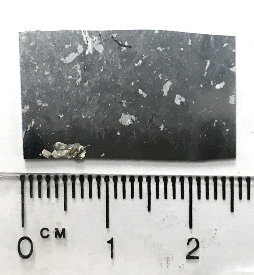
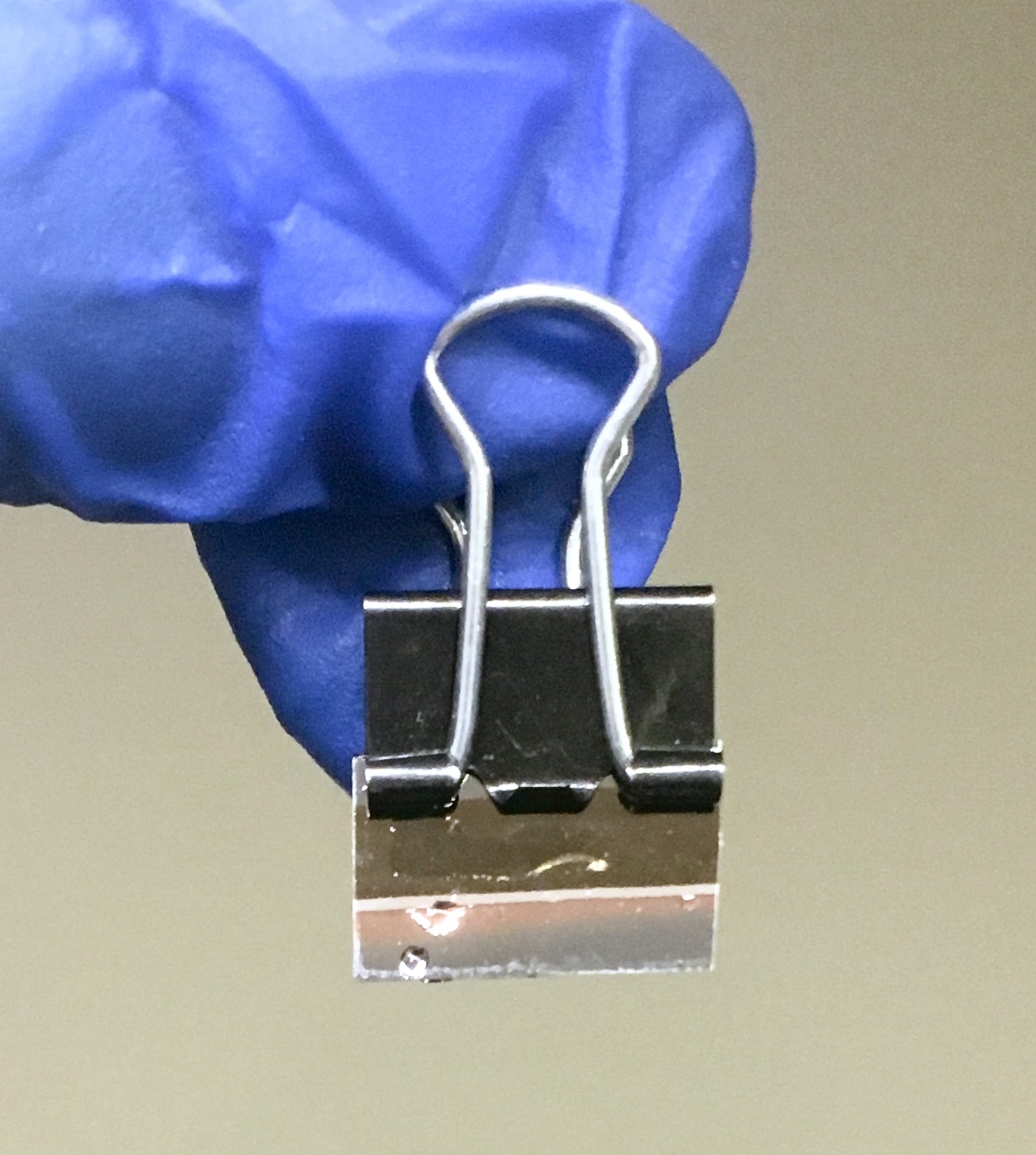
(LEFT) A PVDF-HFP thin film on SiO2 formed by manual Langmuir Blodgett deposition. (RIGHT) A PVDF-HFP thin film formed by automated Langmuir Blodgett deposition. A slight irridescence is visible; always a good sign.
A simple Sawyer-Tower circuit can do the trick for hysteresis measurements, but we used Radiant Ferroelectric tester to evaluate the improvement in thin film quality
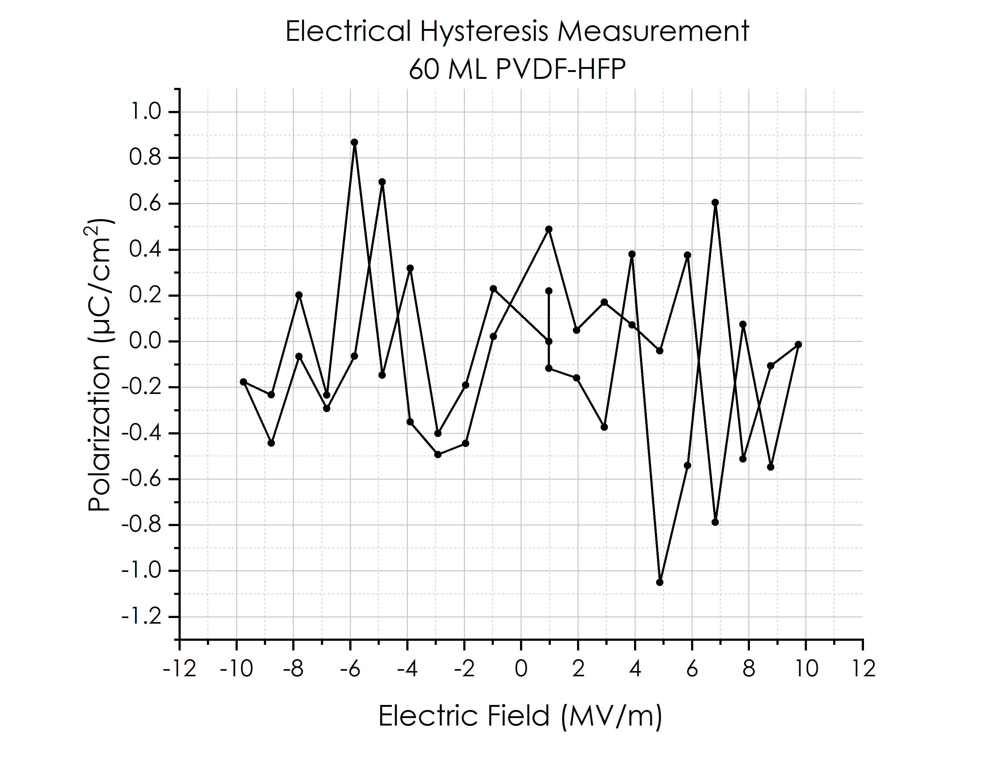
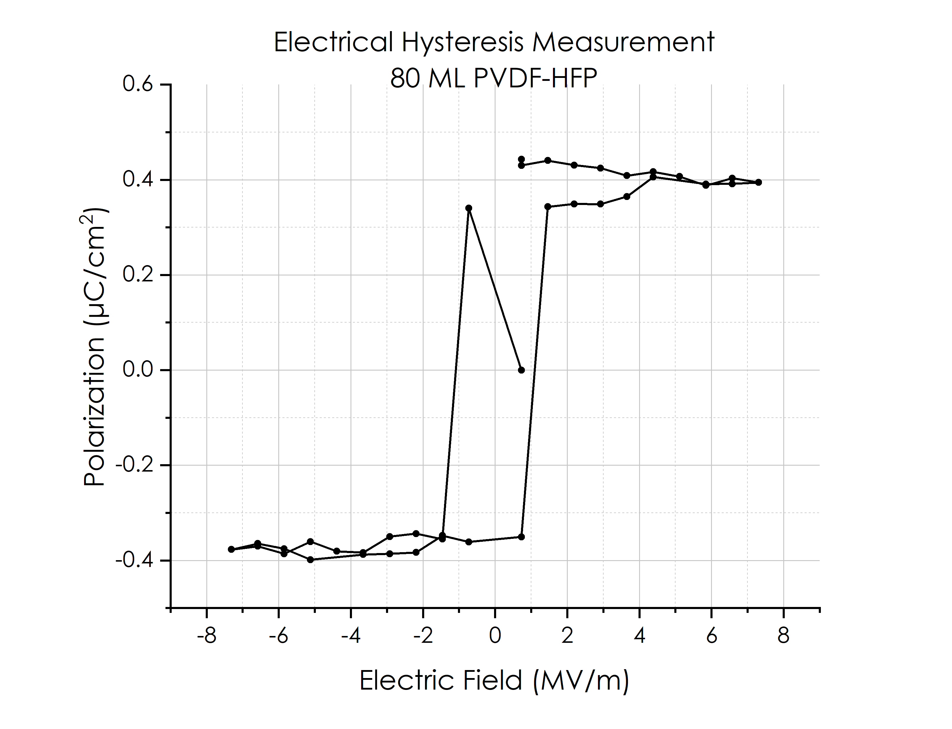
(LEFT) Hysteresis characterization of a PVDF-HFP thin film formed by manual Langmuir Blodgett deposition. (RIGHT) Hysteresis characterization of a PVDF-HFP thin film formed by automated Langmuir Blodgett deposition.